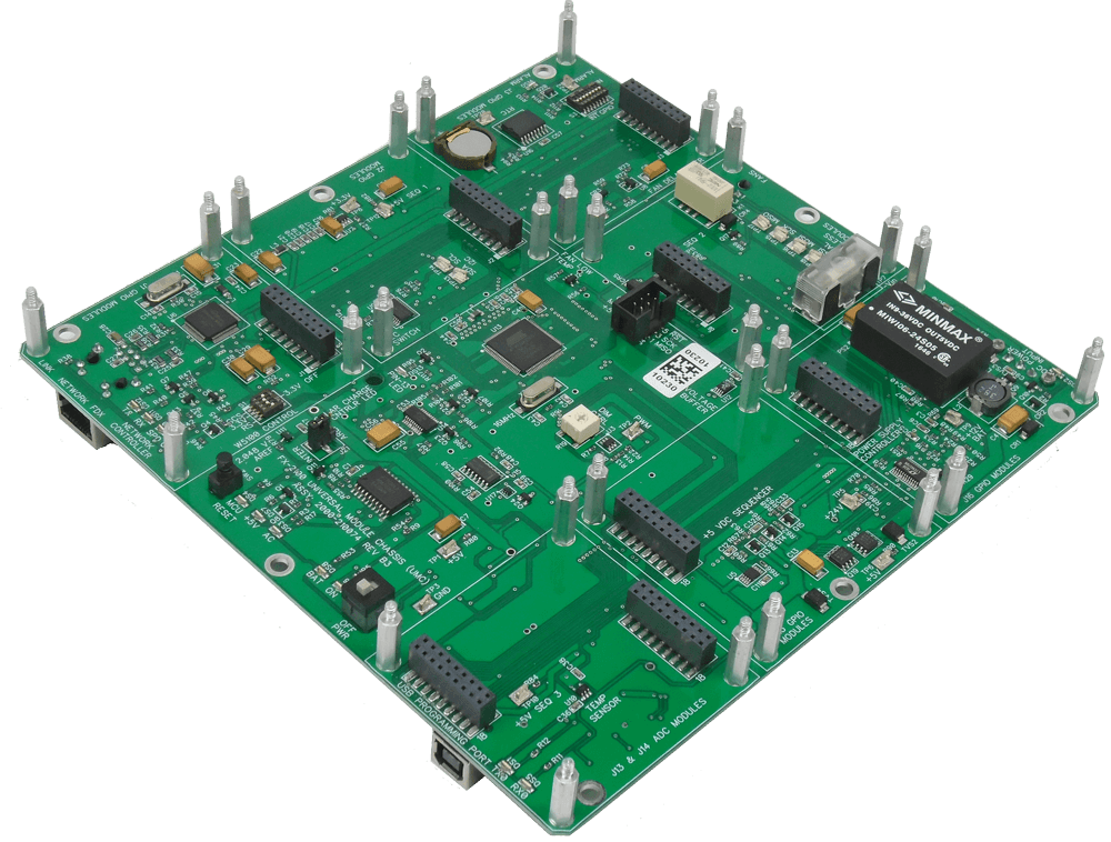
Plug-In I/O Module Positions: Five stackable I/O module positions, one 16-channel 10-bit A/D module position, one serial data/wireless position, (up-to fourteen modules total); one AC UPS or solar electric power position
MICROCONTROLLER UNIT (MCU)
Microchip® ATmega-2560 8-bit AVR microcontroller: 16 MHz clock speed, 256 kB of flash memory, 8 kB of SRAM, and 4 kB of EEPROM; 54-digital input/output pins, with fourteen of the 54-pins capable of serving as pulse width modulator PWM outputs, sixteen 10-bit A/D inputs, and four UARTs (hardware serial data ports)
Clock Speed: 16 MHz crystal controlled (tolerance: ±10 ppm @ 25 °C, stability: ±10 ppm -20 °C to +55 °C)
I/O Access: Connector access to 44 GPIO ports; 16 A/D ports; three serial-data ports; I2C bus with expansion switch allowing up to four-address selections/module position; SPI
USB Programming Connector: Ruggedized USB 2.0 type-B with data line short-to-Vbus protection & IEC ESD protection (IEC 61000-4-2 & ISO 10605 for ±8kV contact discharge & ±15kV air gap); TX & RX LED data activity indicators
USB UART: FTDI FT-231 USB to serial UART interface with 512 byte receive and transmit buffer
In-Circuit Serial Programming (ICSP) Connector: Arduino format six-pin polarized IDC box header (male pins)
USB Programming Connector & Protection: Ruggedized USB 2.0 type-B with short-to-Vbus protection & IEC ESD protection (IEC 61000-4-2 & ISO 10605 for ±8kV Contact Discharge & ±15kV Air Gap)
In-Circuit Serial Programming (ICSP) Connector: Arduino format six-pin polarized IDC box header (male pins)
Isolation: Galvanic isolation of I/O, A/D, serial data ports & AC power supply when using FX-2000 series galvanically isolated modules
DC POWER SUPPLY
Integrated galvanically isolated, overload protected, wide-input voltage range switching DC-to-DC power converter and supervisory circuit system
DC Input Voltage : +10 to +33 VDC, reverse polarity protected (-40 VDC max), transient voltage protection, 1.5 kVDC isolation (input-output), input power LED indicator & user replaceable ceramic cartridge fuse
+5 Volt Output: +5 VDC ±2% @ 5 W, load regulation: ±1%, ripple/noise:< 50 mVpp, supervisory circuit & three stage power-up sequencer, under/over voltage limits, short-circuit protection and, current limit with automatic reset
DC-to-DC Power Converter Standard: UL/cUL/IEC/EN 60950-1 safety approval
Power Supply Switches & Status Indicators: +5 volt power on/off switch; MCU reset pushbutton; individual power supply status LED indicators: DC, AC, BAT & ON
MCU Power Supply Surveillance: 24 VDC supply and battery level A/D buffer-amplifiers (A/D ports 13 & 14)
NETWORK CONTROLLER
Integrated W5100 Internet enabled 10/100 Ethernet controller with TCP/IP stack and integrated Ethernet MAC & PHY and control via the SPI bus
Connector: RJ45 type with 10/100 BASE-TX magnetics (1.5kV isolation)
Power Supply Control: User selectable power on/off control (off-state conserves power in remote solar electric systems)
LED Status Indicators: Link, full duplex, TX, RX, collision, speed & reset
REAL TIME CLOCK (RTC)
Maxim DS3231 extremely accurate real time clock (RTC) with an integrated temperature compensated crystal oscillator (TCXO) and battery back-up system. The RTC maintains seconds, minutes, hours, day, month, and year information. Automatic adjustment for months fewer than 31 days and leap year correction. Operates in either 12 or 24 hour format and includes two user programmable time-of-day alarms.
Time Keeping: Seconds, minutes, hours, day, month, year; leap-year compensated
Calendar Valid: Year 2100
Accuracy: ±2 minutes/year (±3.5 ppm) over the operating temperature range -40˚C to +85˚C
Time-of-Day Alarm: Two user programmable, assignable to 1-of-8 GPIO (8-bit) pins
Control Bus: I2C
Battery Back-Up: Low power battery back-up; user replaceable CR1220 3-volt 35-mAh lithium coin cell
Time Keeping Battery Current/Duration: 3 µA/1-year typical @ 20˚C
GENERAL
LED Illumination Level Control: High–efficiency pulse width modulator (PWM) system, user adjustable 5% to 95% illumination level control for the FX-2100 UMC, I/O and communications module LED status indicators
A/D Voltage Reference (AREF): 2.048 VDC ±0.1%, user on/off configurable
Temperature Sensor: TMP36 temperature sensor, 10 mV/˚C ±2˚C typical (A/D port-15)
Fan On/Off Control: Fan power enabled when any heatsink or relay equipped module output is enabled
Fan Delay Timer & Temperature Operating Limits: FX-2120 Protective Cover cooling fan 10-second off delay ±10 %; fan power disabled below +4˚C and forced on above +48˚C
Test Points: Critical operating test-points for use with standard test probes, clips & hooks
SUPPLIED CABLE & CONNECTOR
USB ATmega-2560 Programming Cable Assembly: USB 2.0 USB-A to USB-B, male, black, 2-meter length, (1010-123548)
DC Power Connector: Plug, Female, 3-position, 3.81 mm pitch, (1010-076621)
PHYSICAL & ENVIRONMENTAL
Size: 7.75” D x 7.75” W x 1.4” H (height includes connectors and standoffs)
Weight: 8 oz
Operating Temperature: -20˚ C to +55˚ C
Humidity: 95% @ +55˚ C