SG9000 RF Signal Generator
The SG9000 RF Signal Generator delivers bench-top performance in a light-weight portable package. Best-in-class phase noise, spectral fidelity, and output power range makes it the perfect choice for measuring SSB, AM, and, FM communication equipment performance in the lab or field environment.
Key Performance Specifications
- 400 kHz to 400 MHz, 1 Hz Step Resolution
- CW, AM, FM & Frequency Sweep (1 ms min dwell time)
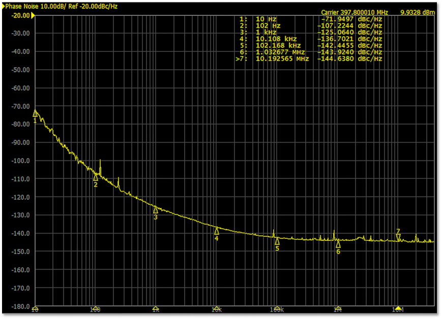
- Excellent Phase Noise Performance: -136 dBc/Hz 10 kHz Offset @ 397.8 MHz with the 020 TCXO Option
- -130 dBm to +10 dBm RF Power Range
- 0.1 dB RF Attenuator Step Resolution
- Spurious Free Dynamic Range: Wide Band: -55 dBc, Narrow Band: -60 dBc (with TCXO Options 020)
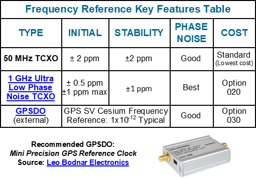
- TCXO ± 0.5 ppb (0.5 ppm) (Standard)
- TCXO ± 1 ppm Ultra Low Phase Noise (Option 020) -136 dBc/Hz 10 kHz Offset @ 397.8 MHz, Typical
- TCXO CAL: Short-Term Accuracy 0.2 ppm, User Cal
- External GPS Disciplined Oscillator (Option 030)
- External RF On/Off & Sweep Start Triggers
Key User Features
- Windows-10/11 User Interface (UI)
- SCPI1 Command Interface
- Small Bench-Top Footprint, Light-Weight, Perfect for Field Service Tasks
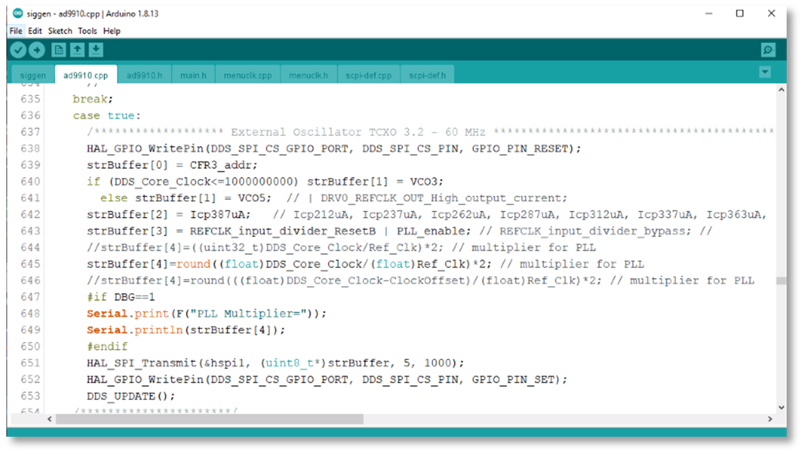
- Open-Source Software, Program in the Arduino Integrated Development Environment (IDE) System
- +30 dBm Reverse RF Power Protection/Alarm & 50 VDC Input Block Protection
- External Sync Output for RF Output On/Off and Frequency Sweep Start
- 10 to 33 Volt DC Power Input, Reverse Polarity Protection & 1.5 kVDC Galvanic DC Source Isolation
- OLED Status Display
Benchtop Performance at a Fraction of the Cost
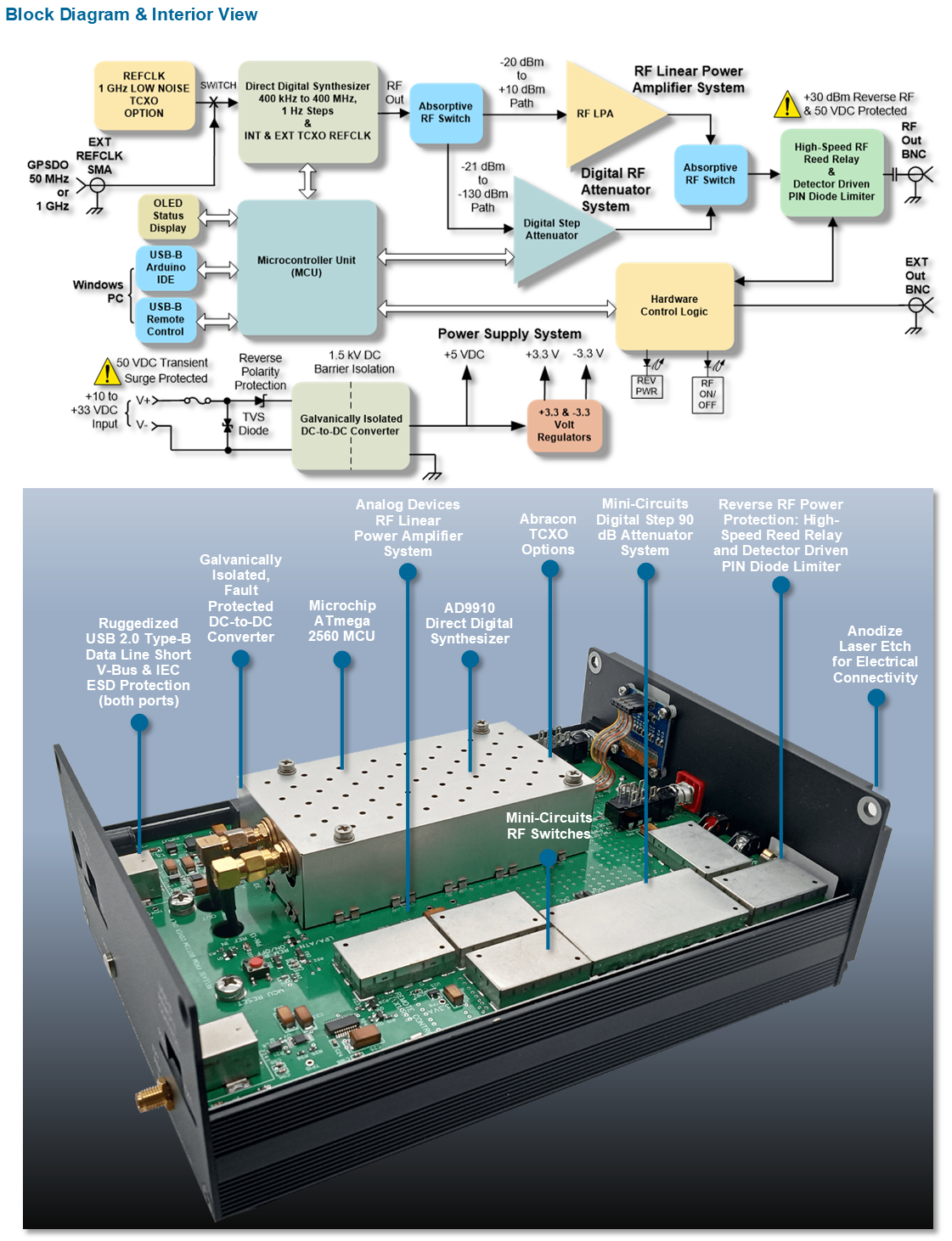
The SG9000 is built on Analog Devices’ high-performance, AD9910 14-bit direct digital synthesizer; Microchip’s ATmega-2560 microcontroller; Abracon TCXOs; Mini-Circuits’ digital-step RF attenuators and RF switches. Combined, these technologies deliver comparable performance to expensive benchtop signal generators at a fraction of the cost.
Windows UI and Open Source Software
Operation is simple and intuitive using the SG9000 Windows remote control application or chose SCPI1 command interface in the LabView environment.
Open source ATmega2560 MCU software developed in the Arduino integrated development environment (IDE) allows you to customize code for your specific test application.
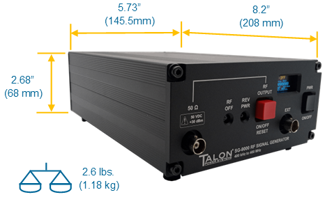
Compact, Rugged, and Portable
The SG9000 is packaged in a compact extruded aluminum enclosure, black anodized finished and laser etched lettering for exceptional appearance and durability. The small form-factor conserves valuable lab bench space while the light-weight ruggedized packaging makes it ideal for field service tasks.
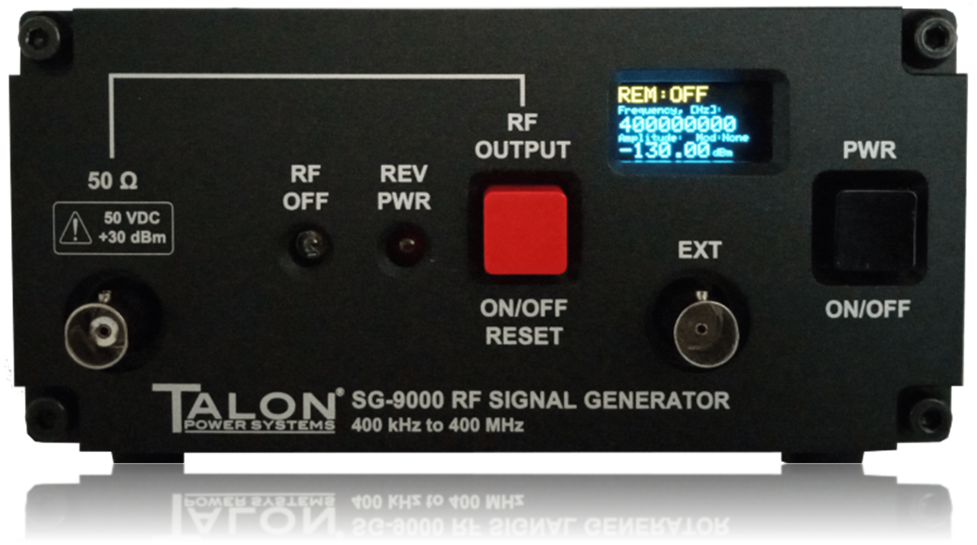
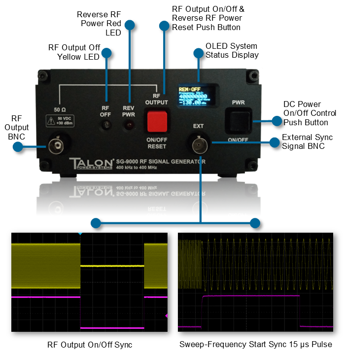
Front Panel Key Operating Features
- RF OFF LED illuminates yellow when the RF output is off
- REV PWR (reverse RF power) LED illuminates red when an external RF power source greater than +20 dBm typical is inadvertently applied to the RF output connector. The RF output remains off until manually reset
- RF OUTPUT push-button switch, duplicates the Windows RF on/off output control function also resets the reverse power latched off state
- Organic LED (OLED) displays the instruments current operating status
- EXT Sync Signal RF Out TTL-high when the RF output is enabled, TTL-low when the RF output is disabled―an excellent aid in evaluating radio receiver AGC attack/release time characteristics.
- EXT Sync Signal Sweep Start TTL-high 15 µs pulse generated at the start of each sweep cycle―perfect for oscilloscope sweep triggering during bode-plot evaluation of filters and networks.
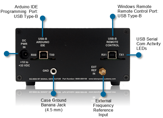
Rear Panel Key Connectivity Features
- DC PWR IN accepts 10 to 33 VDC, reverse polarity/transient protected and galvanically isolated from the input power source
- PROGRAMMING PORT (RX0/TX0) supports Arduino IDE firmware upgrade
- REMOTE CONTROL (RX1TX1) USB-B port, supports the SG-9000 Windows-10 remote control application
- RX0/TX0 & RX1/TX1 Red/green LEDs indicate serial USB Arduino IDE and remote control communications activity
- EXT REF IN, external 40 MHz reference input, -10 dBm typical. Suitable for use with a GPSDO frequency reference source.
- Case Electrical Ground, Banna Jack, 4.5 mm
Windows Remote Control UI
The SG-9000 UI delivers the traditional look and feel of Windows’ instrument control with operation organized in three user selectable tabs:
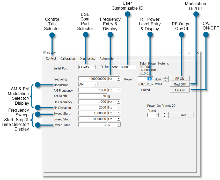
The Control Tab allows you to easily select frequency, modulation, and RF power level and can store the selection configurations in one-of-fifty channel locations with channel-0 serving as the power-on default setting. Additional capabilities include:
- USB Windows Control Port Selection
- RF Output On/Off Control
- RF Output Level in dBm and µV rms
- Link or Unlink the RF Power Level to the Selected Channel
- User Customizable ID to Help Identify Signal Generator Task in a Multi-Generator Application
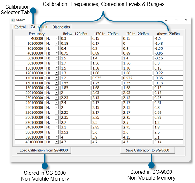
The Calibration Tab allows you to inspect or change the calibration levels, in 0.1 dB steps, as well as the calibration frequencies. The calibration levels/frequency are stored in the SG-9000 non-volatile memory and can be recalled by pressing the Load Calibration from SG-9000 or new values can be stored by pressing the Save Calibration to SG-9000.
Windows Remote Control UI
The Diagnostics Tab allows you to:
- Inspect the standard commands for programmable instruments (SCPI) communications between the Windows control application and the SG-9000
- Select firmware support for the standard 40 MHz TCXO/optional GPSDO reference PLL operation or optional direct 1 GHz TCXO reference operation
- Test the individual digital step attenuators by manually setting and evaluating each attenuator in 0.5 dB steps across the 30.5 dB operating range
- User frequency correction capability. Applies a TCXO offset yielding short-term frequency accuracy of 0.2 ppm.

Software & SCPI Commands
- Open Source ATmegea2560 MCU software developed in the popular, no-cost Arduino integrated development environment (IDE) allows you to customize code for your specific test application
- SCPI commands support all available functions and operating conditions, such as:
FREQuency
POWer
AM:STATe
AM:FREQuency
etc.
AD9910 Frequency Reference
The AD9910 DDS uses a 1 GHz frequency reference, achieved directly by a 1 GHz TCXO or indirectly using the built-in PLL (20X multiplier) and a 50 MHz TCXO. PLL operation also supports the use of an external GPS discipline oscillator (GPSDO) capable of generating a 50 MHz signal. The frequency reference key features table below compares the features and benefits of each type.
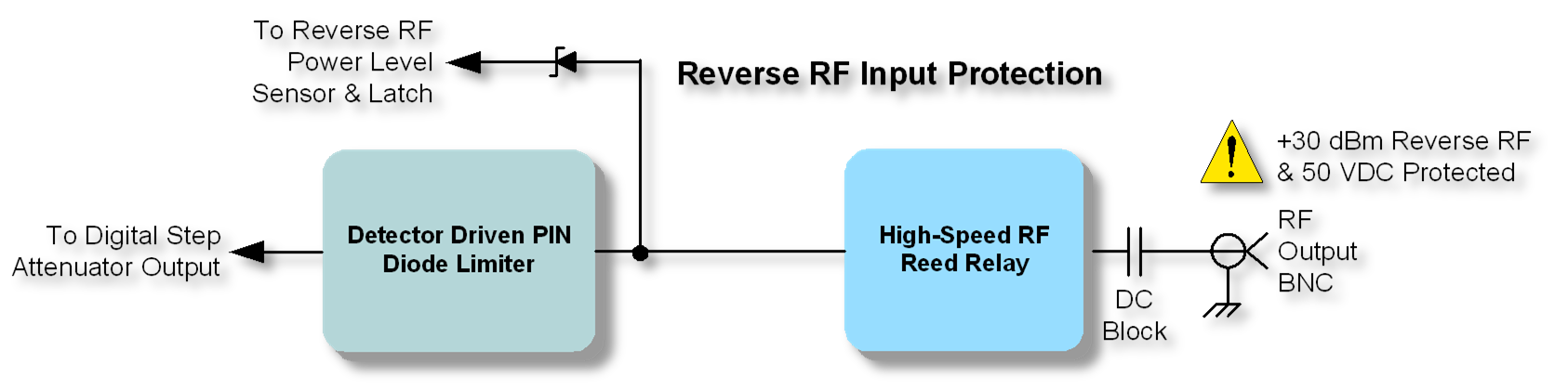
Key Protection Features
- RF Input Protection for the inadvertent application of reverse RF up to +30 dBm is achieved through a high-speed RF reed relay and a detector-driven PIN diode limiter. In operation, levels above +20 dBm will latch the RF output reed-relay open. During the relay’s 0.05 ms transition time, reverse power is clamped to a safe-level by the PIN diode limiter. A series output capacitor blocks DC voltages up to 50 VDC.
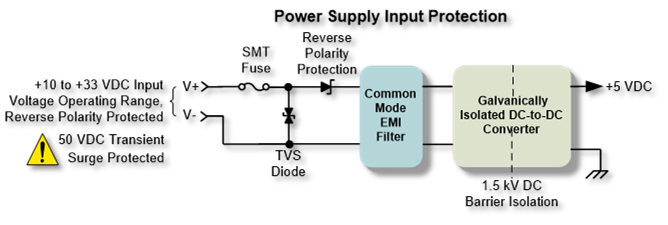
- DC Power Input Protection is provided by a slow-blow fuse, 600-Wpk transient voltage suppressor (TVS) diode, line-to-line and line-to-ground bypass capacitors, a series reverse-polarity Schottky power diode, and common mode EMI filter. In addition, the dc-to-dc converter galvanically isolates the input DC power from the 5-volt system through a 1.5 kVDC rated physical isolation barrier. This rugged input power architecture makes the SG-9000 ideal for field service sites where transient voltage events and ground-loops can materially interfere with and degrade measurement performance.
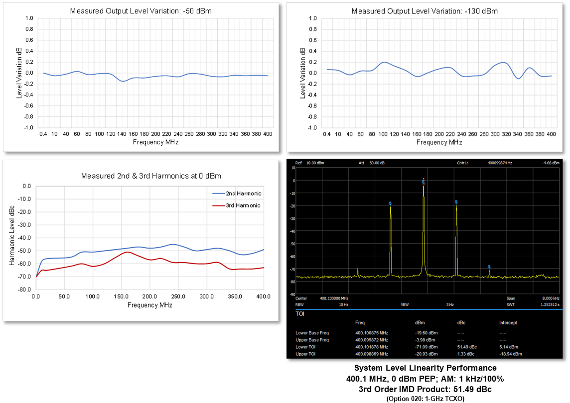
Measured Performance: RF Output Level Variation, Harmonic Content & Linearity
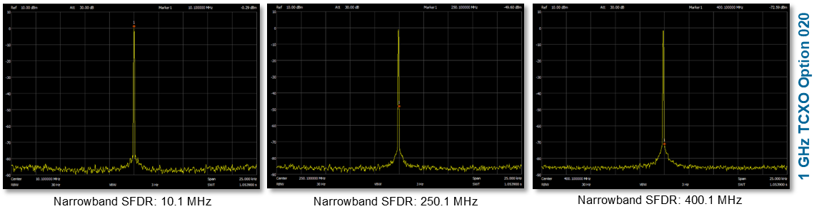
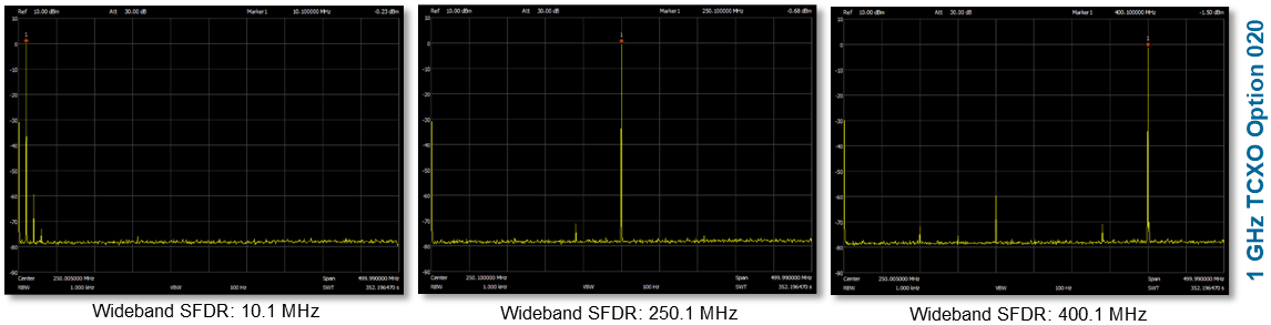
Measured Performance: Spurious Free Dynamic Range (SFDR) 1 GHz TCXO Operation
Performance Specificatiuons
Frequency Range
Range: 400 kHz to 400.0 MHz
Frequency Control Step Resolution: 1 Hz
Channel Storage: 50 channels
Frequency Reference Clock
Standard: 50.0 MHz ± 2.0 ppm TCXO
Initial Calibration: ± 1 ppm
Aging / Year: ± 1 ppm, Max: ± 6 ppm over 10-years
Over Temperature Range: ± 0.5 ppm
Option 020: 1 GHz ± ppm Ultra Low Phase Noise TCXO
Initial Calibration: ≤ ± 1 ppm typical, ± 1.5 ppm max
Aging / Year: ± 1 ppm after 1-year
Over Temperature Range: ± 1 ppm
Option 030: GPSDO
RF Power Level & Control
Power Range: -130 dBm to +10 dBm (AM 100 % Modulation & +4 dBm Carrier = +10 dBm PEP max), 50-Ohm
Step Resolution: 0.1 dB
Level Uncertainty: +10 dBm to -130 dBm: ≤ 1.1 dB
Level Stability: ≤ ±0.1 dB over 8-hours
VSWR: < 1.8:1 nominal (RF output BNC connector)
RF Output-Off Residual Level: ≤ -135 dBm
RF Range Calibrator Capability: 0 dBm ± 0.1 dB; 50 MHz
RF Output Control: Front panel switch and remote control with yellow LED RF off annunciator
RF Output Trigger: TTL-high RF output on, TTL-low RF output off (Front Panel EXT BNC connector); Trigger TTL high RF-on delay: 26 µs, RF-off trigger TTL low delay: 123 µs
Reverse RF Power & DC Voltage Protection
Maximum Reverse RF Input Power: +30 dBm, trip threshold +20 dBm typical, RF output open-circuit when tripped with reverse power annunciator red LED, front panel resettable
Maximum DC Input Voltage: 50 VDC
Power Off, RF Output Circuit Condition: Open circuit
Spectral Purity
Narrow-Band (25 kHz) Spurious Free Dynamic Range: -50 dBc (-60 dBc with 1 GHz REFCLK 020 option)
Wide-Band (400 kHz to 500 MHz) Spurious Free Dynamic Range: -45 dBc (-55 dBc with 1 GHz REFCLK 020 option)
Harmonics: 2nd: ≤ -40 dBc, 3rd: ≤ -45 dBc
SSB Phase Noise:
50 MHz TCXO*: -129 dBc/Hz typical, Fc = 398.7 MHz, 10 kHz offset
1 GHz TCXO Option 020: -136 dBc/Hz typical, Fc = 398.7 MHz, 10 kHz offset
* Design Objective, Pending Measurement Validation
PLL 50 MHz Reference Oscillator Feed-Thru, Fundamental & Harmonics Products: < -130 dBm
Amplitude Modulation (AM)
Frequency Range: 10 Hz to 100 kHz in 1 Hz steps
Modulation Depth: 0% to 100% in 1% steps
Max Linear AM Power: 100 % Modulation & +4 dBm Carrier = +10 dBm PEP max), 50-Ohm
Frequency Modulation (FM)
Frequency Range: 10 Hz to 100 kHz in 1 Hz steps
Frequency Deviation Range: 0 Hz to 100 kHz in 1 Hz steps
Frequency Sweep
Sweep Type: Linear
Sweep Range: Full frequency range, Start Frequency Error: As Calibrated, Stop Frequency Error: 5 ppm Typical
Sweep Mode: Continuous
Dwell Time Range: 1 ms to 10s, ± 3.5%
Dwell Time Resolution: 1 ms
Trigger Output: 15 µs TTL-high pulse at the low-frequency sweep start (EXT connector)
Sweep On/Off Control: Windows remote control UI Sweep On/Off button or SCPI control
Remote Control Protocol & Software
Remote Control Protocol: Standard Commands for Programmable Instruments (SCPI)
Windows SG-9000 remote controlled software supplied
System Firmware: Arduino open source
USB Communications
USB Arduino IDE Port: Ruggedized USB 2.0 Type-B with data line short to V-bus protection & IEC ESD protection (IEC 61000-4-2 & ISO 10605 for ± 8kV contact discharge ± 15 kV air gap, TX & RX LED communications activity indicators. Com, bps: 9600; bits: 8; parity: none; stop bit: 1
USB Remote Control Port (Arduino RX1 & TX1): Ruggedized USB 2.0 Type-B with data line short to V-bus protection & IEC ESD protection (IEC 61000-4-2 & ISO 10605 for ± 8kV contact discharge ± 15 kV air gap, TX & RX LED communications activity indicators. Com, bps: 9600; bits: 8; parity: none; stop bit: 1
Power Supply System
DC Power Converter: Switching DC-to-DC power converter
DC Input Voltage Operating Range: 10 to 33 VDC
DC Input Current Consumption (12 VDC @ 0 dBm): 315 mA typical, power-off: 25 mA typical
Converter Protection: 1.5 kVDC galvanic input/output isolation; under voltage, overload, short-circuit protection, and input transient voltage protection; internal PCB SMT DC fuse
DC Power Jack: 2-Pin, 5.5 mm outer, 2-mm center-pin + polarity
AC Wall Mount Power Supply: AC transformer/bridge rectifier, 18 VDC 9 W output, 120 VAC ± 20%, 50-60 Hz Input, 72” cable length with mating 5.5 mm DC power plug
Front Panel Connectors, Switches & Indicators
RF Output Connector: BNC female, 50-Ohm, unbalanced
RF Output/Reverse Power Reset Switch: Alternate push-on/push-off
RF Off Indicator: LED illuminated yellow (RF on: extinguished)
Reverse Power Indicator: LED illuminated red
DC Power Switch: Alternate push-on/push-off
EXT Output Connector: BNC female, RF output on TTL high, or 15 µs TTL pulse at sweep low frequency start
Rear Panel Connectors
USB Arduino IDE: USB Type-B
Remote Control (RX1/TX1): USB Type-B
EXT REF IN: SMA female, external reference clock input
DC Power In: 2-Pin, 5.5 mm with 2-mm center pin
General Specifications
Dimensions: 8.19” L x 5.73” W x 2.68” H (208 mm L x 145.5 mm W x 68 mm H)
Weight: 2.3 lb. (1.1 kg)
Temperature, Operating: 5˚C to 45˚C; Storage: -20˚ C to 70˚ C
Humidity: 0˚ C to 30˚ C <95% relative humidity
All specifications are warranted performance specifications with guaranteed tolerance limits using the standard supplied 40 MHz TCXO frequency reference unless otherwise noted.
Specifications are valid if the instrument is within the calibration period, has been powered-on for at least 45-minutes, and the operating environment ambient temperature is between 18˚C and 28˚C unless otherwise noted.
Nominal refers to the features or characteristics of the design.
Typical indicates that 80% of units will meet the published typical performance with 80% confidence, unless otherwise noted. Typical performance is not warranted.